
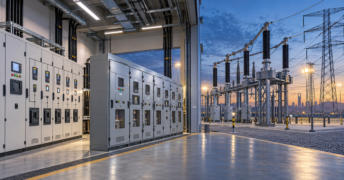
Low-voltage switchgear is generally used for electrical distribution up to 1,000 volts AC, medium-voltage switchgear manages distribution above 1 kV across facilities and local networks, and high-voltage switchgear is used primarily in substations and power-transmission systems. The correct type depends on the system voltage, fault level, load, application and applicable project standards.
Choosing between LV, MV and HV switchgear is not simply a matter of selecting a larger or more powerful enclosure. Each voltage class performs a different role within the electrical network and requires different equipment, insulation, protection systems, installation practices and safety procedures.
This guide compares low-, medium- and high-voltage switchgear and explains which type may be appropriate for commercial buildings, industrial facilities, infrastructure projects, utilities and power-generation applications.
The main difference between LV, MV and HV switchgear is the rated voltage of the electrical system in which it operates. As voltage increases, the insulation, fault-interruption, protection, testing and operator-safety requirements become more demanding.
Low-voltage switchgear commonly operates at up to 1 kV AC. Its principal role is the final distribution of electricity to building services, machinery, lighting systems and other electrical loads.
Medium-voltage switchgear operates above 1 kV and commonly up to 36 kV in many practical applications. It distributes electricity between incoming supplies, substations, transformers and large facilities.
High-voltage switchgear operates above the applicable medium-voltage range. It is mainly used for bulk power transmission, major substations and utility-grid control.
These boundaries can vary by country, utility and technical standard. Some standards classify equipment above 1 kV under the broader high-voltage category, while the electrical industry commonly uses “medium voltage” for practical distribution levels between LV and transmission-class HV.
The project’s approved single-line diagram and specifications should define the required rated voltage rather than relying only on general labels.
For a broader introduction, read What Are the Types of Switchgear? LV, MV and HV.
Low-voltage switchgear controls, protects and distributes electricity in systems operating at up to 1,000 volts AC.
It is normally installed downstream of a distribution transformer, where medium voltage has been stepped down to a usable level such as 400/230V. It then distributes power to building services, machinery, lighting, HVAC systems and other final loads.
LV switchgear may include:
These components may be arranged within main distribution boards, sub-main distribution boards, motor control centres or other low-voltage assemblies.
Low-voltage switchgear is commonly used in:
A large industrial facility may use MV switchgear at its incoming supply while still using multiple LV assemblies downstream. Choosing MV does not remove the need for LV distribution; the two commonly operate at different stages of the same electrical system.
You generally need LV switchgear when the supplied equipment operates at standard utilisation voltages and the electrical system is already downstream of a step-down transformer.
The final selection must account for more than voltage. Engineers must also determine:
Low voltage does not mean low risk. LV systems can carry very high currents and release significant energy during a short circuit or arc-flash incident.
Medium-voltage switchgear controls and protects electrical distribution systems operating above 1 kV and, in many IEC-based applications, commonly up to 36 kV. Some regional practices extend the MV designation to higher levels.
MV switchgear is positioned between high-voltage transmission and low-voltage utilisation. It allows electricity to be distributed efficiently across large sites before transformers reduce it to the voltage required by equipment and building loads.
The IEC 62271 family covers alternating-current switchgear and controlgear with rated voltages above 1,000V. The relevant part of the standard depends on the equipment design and application.
MV systems may include:
To understand the role of these devices, read What Are Switchgear Components and Their Functions?.
Medium-voltage switchgear is commonly found in:
Alrouf project data includes MV and LV switchgear within integrated electrical packages for airport, water-infrastructure, industrial and landscape-lighting projects. Examples of project distribution levels include 13.8 kV and 33 kV on the MV side, followed by 400/230V LV distribution. These are project examples, not universal voltage requirements.
MV switchgear is usually required when a facility receives power at a medium-voltage service level or needs to distribute substantial power efficiently across a large site.
It may be appropriate when:
An engineer must confirm the system voltage, normal current, short-circuit level, internal arc requirements, insulation level, service continuity and protection philosophy before specifying the equipment.
High-voltage switchgear controls, protects and isolates transmission-level electrical systems and major substations.
It is normally associated with utilities, power plants, grid interconnections and large transmission networks rather than final distribution inside an ordinary commercial or industrial building.
HV switchgear must safely interrupt extremely high fault currents while maintaining insulation across large electrical clearances. Its engineering, installation, testing and maintenance require specialised expertise.
HV installations may use:
High-voltage switchgear is primarily used in:
Most individual buildings do not receive power directly at high-voltage transmission levels. They are normally supplied through utility substations that reduce the voltage before it reaches the site’s MV or LV distribution system.
HV switchgear is needed when the project forms part of a transmission-level network or connects to a utility system at a voltage above the applicable MV range.
The decision is normally established by the utility connection agreement, network study and approved substation design. HV switchgear is not selected independently as a substitute for LV or MV equipment.
HV projects require detailed coordination between the utility, engineering consultant, system integrator, equipment manufacturer and testing specialists.
LV, MV and HV switchgear differ in their purpose, location within the network, protection requirements and installation complexity.
LV switchgear handles final electrical distribution and equipment control. It is normally installed downstream of transformers and supplies building services, industrial equipment and final electrical loads.
It typically uses circuit breakers, fuses and electronic protection units. Its insulation requirements are lower than those of MV and HV equipment, although LV systems may carry comparatively high current.
LV switchgear generally has the lowest installation complexity and cost of the three classes. Its common forms include distribution boards and motor control centres.
MV switchgear distributes electricity across large sites and local networks. It is commonly positioned between the incoming electrical supply and the transformers that feed LV systems.
Its protection arrangement normally includes protective relays, circuit breakers and instrument transformers. Compared with LV equipment, it requires higher insulation levels, more specialised operating procedures and personnel trained to work with medium-voltage systems.
MV equipment commonly takes the form of metal-enclosed switchgear line-ups or ring main units. Its installation complexity and cost are normally higher than those of LV switchgear.
HV switchgear is used for bulk power transmission and grid control. It is normally located in transmission substations, power-generation switchyards and utility interconnections.
Its systems may include advanced protection, control and substation-automation technologies. HV equipment requires the highest insulation levels, specialised engineering and highly trained personnel.
Its physical form can range from large outdoor substation equipment to compact gas-insulated switchgear. HV installations are generally the most complex and expensive because of their voltage, fault-interruption and safety requirements.
Actual equipment size, cost and complexity depend on current, fault level, insulation medium, installation environment and project requirements.
The voltage supplied by the utility or generated by the facility is the first factor. A project should not select LV, MV or HV switchgear based only on building size or estimated power demand.
Many large projects need more than one class. A utility supply may enter through MV switchgear, feed several transformers and then continue through LV switchgear to individual loads.
Voltage classification only identifies the general equipment category. A compliant specification must address the complete system.
The switchgear must continuously carry the expected current without exceeding permitted temperature-rise limits.
Rated current is determined by the electrical load, system voltage, diversity and operating conditions. It should also account for future expansion where required.
The assembly and its protective devices must withstand and interrupt the maximum prospective fault current at the installation point.
This value should be established through a short-circuit study. Selecting switchgear with an insufficient rating can expose equipment and personnel to serious risks during a fault.
Circuit breakers, fuses and protective relays should be coordinated so that the device closest to a fault operates first whenever practical.
Correct coordination limits the affected part of the network, reduces unnecessary shutdowns and helps maintain service for unaffected loads.
MV and HV projects may require tested internal arc classification to reduce risks associated with an internal arcing fault.
The required classification must be defined by the project’s risk assessment, installation arrangement, accessibility conditions and applicable standards.
Switchgear may use air, gas, solid insulation or a combination of technologies.
The correct option depends on:
The design must consider:
Saudi projects may require particular attention to high temperatures, dust, sand and coastal corrosion.
Withdrawable breakers, sectionalised busbars and redundant incoming supplies can improve maintenance access and operational continuity.
However, these arrangements may increase the required space, system complexity and project cost. The solution should reflect the importance of the connected loads and how much downtime the facility can tolerate.
Digital protection relays, energy meters, temperature monitoring and communication systems can support:
For a complete explanation of protection, control and isolation, visit How Does Switchgear Work? A Complete Guide.
No. Higher voltage does not mean that the equipment is automatically better, more efficient or more suitable for every project.
Voltage must match the electrical network. Installing equipment with an unnecessarily high voltage class increases cost, space, insulation requirements and operational complexity without providing a useful benefit.
Using a voltage class below the system requirement is unsafe and unacceptable. Correct selection means matching the equipment’s rated voltage and performance to the approved electrical design.
HV switchgear generally has the highest equipment and project cost, followed by MV and then LV. However, voltage class alone does not determine the final price.
Major cost factors include:
LV switchgear generally has lower insulation and installation requirements, but large LV systems may still be costly when they require high current ratings, advanced protection, multiple feeders or extensive automation.
MV switchgear normally costs more because it requires higher insulation, specialised breakers, protective relays, instrument transformers and trained installation personnel.
HV switchgear generally involves the greatest investment because it forms part of a transmission-level system and requires specialised substation engineering, protection, testing and commissioning.
MV distribution may reduce current and cable requirements when transmitting large amounts of power across a site. Therefore, an MV-LV architecture can sometimes be more practical than attempting to distribute all power at low voltage.
A lifecycle assessment should consider capital cost, energy losses, reliability, maintenance, expansion and downtime rather than comparing panel prices alone.
To receive an accurate technical proposal, provide:
When some information is unavailable, a qualified electrical engineer should complete the required system studies before procurement.
The single-line diagram is particularly important because it shows how the incoming supply, switchgear, transformers, generators, busbars and outgoing feeders are connected.
Providing complete technical information helps the supplier prepare an accurate proposal and reduces the risk of receiving equipment that does not match the electrical system.
Yes. In common industry practice, 11 kV is considered medium voltage and is widely used for local power distribution and industrial facilities.
In many practical distribution systems, 33 kV is described as medium voltage. Classification can vary by standard and utility, so the project documentation should define the applicable category.
Yes. Many large facilities receive electricity through MV switchgear, use transformers to reduce the voltage and distribute it through LV switchgear to final loads.
The IEC 61439 series establishes requirements for low-voltage switchgear and controlgear assemblies. The applicable part depends on the type and use of the assembly.
The IEC 62271 series covers high-voltage switchgear and controlgear above 1,000V, including equipment commonly described in the industry as medium voltage. The applicable part depends on the equipment type.
Yes. A ring main unit is typically a compact form of medium-voltage switchgear used in ring-distribution networks to switch, protect and isolate feeders and transformers.
A distribution board is generally an LV assembly that divides an incoming electrical supply into outgoing circuits.
Switchgear is a broader term covering equipment used to switch, protect, control and isolate electrical systems across different voltage levels.
Hazardous-area installations require equipment and enclosures appropriate for the classified zone, gas or dust group, temperature class and protection concept.
The area-classification study and project specifications must guide the selection. Standard electrical enclosures should not automatically be assumed suitable for locations containing flammable gases, vapours or combustible dust.
Selecting LV, MV or HV switchgear begins with the electrical system design. The correct solution must match the voltage, load, fault level, protection philosophy, installation environment and applicable standards.
Alrouf Lighting Technology Ltd. supports electrical and infrastructure projects with switchgear and distribution equipment as part of integrated electrical packages. The scope should be confirmed against the project drawings and technical specifications before equipment is proposed.
Explore Alrouf’s Electrical Switchgear solutions or contact the technical team with your single-line diagram, voltage level, fault rating and project requirements to request suitable technical support and a project-specific quotation.
