
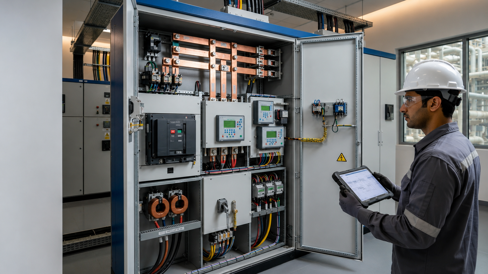
Switchgear contains electrical switching, protection, control, measurement, and isolation devices that work together to distribute power safely. Its principal components include circuit breakers, protection relays, busbars, disconnectors, fuses, instrument transformers, earthing switches, surge-protection devices, meters, control circuits, and protective enclosures.
Understanding the function of each component helps electrical engineers, consultants, contractors, and facility managers specify, operate, and maintain switchgear more effectively.
Switchgear is an assembly of electrical devices used to control, protect, and isolate circuits and equipment. During normal operation, it directs electrical power to the required loads. When an overload, short circuit, earth fault, or another abnormal condition occurs, the protection system detects the problem and disconnects the affected circuit.
Switchgear may be installed in low-voltage, medium-voltage, or high-voltage networks. The components and their ratings vary according to the system voltage and application, but the fundamental operating sequence remains similar: measure the electrical condition, detect abnormalities, interrupt the current, and isolate the circuit safely.
The main switchgear components can be divided into six functional groups:
Each group performs a different role, but all components must operate as one coordinated system.
A circuit breaker opens or closes an electrical circuit and interrupts current when a fault occurs. During normal operation, its contacts remain closed so current can pass. When the protection system issues a trip command, the contacts separate and the breaker extinguishes the electrical arc created during interruption.
Common circuit breakers include:
A circuit breaker must be selected according to the system voltage, continuous current, prospective fault current, breaking capacity, and required protection characteristics.
A breaker that can carry the normal load but cannot safely interrupt the available short-circuit current is not suitable for the installation.
A protection relay monitors electrical conditions and determines when a circuit breaker should trip. It receives signals from current transformers and voltage transformers, compares the measured values with programmed settings, and sends a trip command when it detects a fault.
Depending on the electrical system, protection relays may detect:
Modern numerical relays can combine several protection functions in one device. They may also record fault events, store measurements, and communicate with supervisory systems for remote monitoring.
The relay and circuit breaker have different responsibilities: the relay identifies the fault and decides when to trip, while the circuit breaker physically interrupts the current.
A busbar is a conductive bar that collects and distributes electrical power between the incoming supply and outgoing circuits. Busbars are normally manufactured from copper or aluminium and are supported and insulated inside the switchgear assembly.
Important busbar characteristics include:
During a major fault, electromagnetic forces can place severe mechanical stress on the busbar system. The busbars, joints, and supports must therefore withstand both the thermal and mechanical effects of the specified short-circuit current.
An earth bus is different from the main busbar. The main busbar distributes operational power, while the earth bus provides a continuous protective earthing path throughout the assembly.
A circuit breaker interrupts normal load current and fault current, while an isolator—also called a disconnector—creates a secure separation between an isolated circuit and its electrical supply.
In a typical maintenance procedure, the circuit breaker opens first to interrupt the current. The isolator is then opened to establish isolation.
An ordinary isolator should not be used to interrupt fault current, and it should not be operated under load unless it is specifically designed for that duty.
A load-break switch can interrupt normal load current, but its fault-interruption capability is generally more limited than that of a circuit breaker. The exact switching duty must always be confirmed from the device rating and system design.
An earthing switch connects an isolated conductor to earth. It discharges residual or induced voltage and helps establish safer working conditions before maintenance begins.
Earthing switches are particularly important in medium- and high-voltage switchgear, where cables and equipment may retain an electrical charge or become energised by induction.
Earthing switches are normally coordinated with circuit breakers and disconnectors through mechanical or electrical interlocks. These interlocks help prevent unsafe operations, such as:
The earthing switch must be correctly rated for the electrical system and operated only by qualified personnel following approved safety procedures.
A current transformer, or CT, converts a high primary current into a lower standardised secondary current that can be measured safely by meters and protection relays.
Current transformers are used for:
Protection CTs must reproduce fault current accurately enough for the protection relay to operate correctly. Metering CTs are selected to provide accurate measurements within their intended operating range.
A CT secondary circuit should not be left open while the primary circuit is energised because a hazardous voltage may develop across its secondary terminals. CT circuits should only be handled by qualified personnel following an approved safety procedure.
A voltage transformer, also called a VT or potential transformer, reduces system voltage to a standard level suitable for protection relays, meters, and control equipment.
Voltage-transformer signals can support:
Current transformers reproduce current conditions, while voltage transformers reproduce voltage conditions. Together, they give the protection and monitoring system the information needed to assess the electrical network.
A fuse protects a circuit by melting when excessive current passes through its element. This opens the circuit and limits the effects of an overload or short circuit.
Fuses may be used for:
High-rupturing-capacity fuses can safely interrupt substantial fault currents when correctly selected. Unlike a circuit breaker, however, a fuse normally needs to be replaced after it operates.
Fuse selection must consider rated voltage, rated current, breaking capacity, utilisation category, and coordination with upstream and downstream protection devices.
A contactor is an electrically operated switching device designed for frequent control of electrical loads.
Contactors are commonly used for:
A contactor allows a load to be controlled remotely or automatically. However, it is not normally intended to clear a major short circuit by itself.
Circuit breakers or fuses provide short-circuit protection, while overload relays may protect motors against sustained overloads. This coordinated arrangement allows the contactor to perform routine switching while separate protection devices respond to abnormal current.
Surge arresters and surge-protection devices limit transient overvoltages before they damage insulation or connected equipment.
Transient voltages may result from:
Surge-protection devices are commonly installed in low-voltage assemblies. Surge arresters perform a similar protective role in medium- and high-voltage systems.
Their selection depends on the system voltage, earthing arrangement, expected surge conditions, and insulation withstand level of the protected equipment.
Meters and sensors provide operators with information about the condition and performance of the electrical system.
A switchgear assembly may include:
Monitoring data can help operators identify excessive loading, phase imbalance, abnormal temperature, deteriorating connections, and unusual switching activity.
When the information is integrated with a building management system or SCADA platform, authorised personnel may monitor equipment, measurements, alarms, and fault events remotely.
Trip coils, closing coils, and auxiliary contacts form part of the switchgear control system.
A trip coil releases the breaker mechanism so the circuit breaker opens. It may receive its operating command from a protection relay, control switch, emergency system, or remote-control system.
A closing coil electrically closes the circuit breaker when the required control and safety conditions have been satisfied.
Auxiliary contacts indicate whether a breaker or switch is open, closed, connected, isolated, or tripped. They can also provide information to interlocking, alarm, BMS, and SCADA systems.
Selector switches allow authorised operators to choose between operating modes, such as local and remote control.
Indication lamps may display equipment position, voltage presence, alarm conditions, or trip status.
Control circuits may operate from AC or DC supplies. Their reliability is essential because the main circuit breaker may depend on the control system to open during a fault.
Interlocks restrict equipment operation unless the required safety conditions have been met. They help prevent incorrect switching sequences and reduce the risk of exposing personnel or equipment to energised conductors.
Common interlocking arrangements may prevent:
Interlocks may be mechanical, electrical, or key-operated. They support safe operation, but they do not replace approved procedures, isolation verification, personal protective equipment, or qualified personnel.
The switchgear enclosure protects people from accidental contact with energised parts and protects internal equipment against environmental conditions.
It also supports:
Depending on the design, an enclosure may provide separate compartments for:
The required enclosure design depends on whether the switchgear is installed indoors or outdoors and on its expected exposure to dust, water, heat, humidity, and corrosive conditions.
The IP rating indicates the degree of protection against solid objects and water. However, an IP rating does not by itself define the switchgear’s ability to withstand or contain an internal arc.
During an electrical fault, switchgear components operate in a coordinated sequence:
The speed and selectivity of this sequence are important. A coordinated protection system should disconnect the faulty section quickly without unnecessarily shutting down unaffected circuits.
Switchgear components must be selected as part of a complete engineered assembly, not as unrelated individual devices.
Important selection factors include:
Compatibility between components is essential. The circuit breaker, relay, instrument transformers, busbars, control supply, and mechanical assembly must be designed and tested to operate together under normal and fault conditions.
The applicable standards depend on the voltage level, equipment type, installation location, and project requirements.
Common references include:
The latest applicable editions and any Saudi, utility, or project-specific requirements should be confirmed during specification and procurement.
Regular inspection and maintenance help ensure that switchgear components will operate when required.
Maintenance activities may include:
The maintenance programme should follow the manufacturer’s instructions, equipment condition, operating history, and applicable safety procedures.
Testing or internal inspection must only be performed by qualified personnel after the equipment has been isolated, proved de-energised, and earthed where required.
Common switchgear problems can include loose connections, worn contacts, insulation contamination, failed control circuits, incorrect relay settings, overheating, and mechanical operating problems.
Possible warning signs include:
These warning signs should be investigated promptly by qualified personnel. Switchgear should never be opened or inspected internally while energised unless the equipment, procedure, and personnel are specifically authorised for that work.
Reliable switchgear depends on the coordination of every component. Circuit breakers interrupt current, relays detect faults, busbars distribute power, instrument transformers provide measurements, isolators and earthing switches support safe maintenance, and enclosures protect both equipment and personnel.
When planning a new electrical distribution system or upgrading an existing installation, the switchgear should be specified according to the actual network study, fault level, load requirements, operating environment, and applicable standards.
Contact Alrouf to discuss the switchgear requirements of your commercial, industrial, or infrastructure project.
The main components include circuit breakers, protection relays, busbars, disconnectors, fuses, current and voltage transformers, earthing switches, contactors, surge-protection devices, meters, control circuits, interlocks, and enclosures.
No single component can provide every switchgear function. The circuit breaker interrupts current, but it depends on relays and instrument transformers for fault detection. Safe and reliable operation requires all components to be correctly coordinated.
A protection relay detects abnormal electrical conditions and sends a trip command. The circuit breaker receives that command and physically interrupts the current.
A circuit breaker is designed to interrupt normal and fault current within its rating. An isolator provides separation for safe isolation and is normally operated only after current has been interrupted.
A busbar collects and distributes electrical power between incoming and outgoing circuits. It must carry the rated current and withstand the thermal and mechanical effects of the specified short-circuit current.
Current transformers and voltage transformers reduce high current and voltage values to standardised signals that protection relays and meters can use safely.
Instrument transformers measure the fault, the protection relay detects it, and the relay activates the breaker trip coil. The circuit breaker then opens and interrupts the fault current while alarms and monitoring systems report the event.
An earthing switch connects an isolated circuit to earth. It helps discharge residual or induced voltage and establishes safer conditions for maintenance after isolation has been verified.
Yes. Compatible digital relays, meters, and controllers can communicate operating status, measurements, alarms, and fault information to a BMS or SCADA system. The available functions depend on the switchgear design and communication architecture.
Circuit breakers, disconnectors, earthing switches, protection relays, busbar connections, cable terminations, control circuits, batteries, sensors, and enclosure systems may all require inspection or testing according to the manufacturer’s recommendations and operating conditions.
